
How to Prevent Porosity in Pressure Vessel Welds
How to Systematically Prevent Porosity in Pressure Vessel Welding
For welding supervisors and quality assurance teams, few defects are as persistent or costly as porosity. In the high-stakes world of pressure vessel fabrication, a weld riddled with gas pores is more than a cosmetic issue—it's a critical failure point that can lead to costly rework, project delays, and compromised structural integrity. Achieving consistently clean, sound welds demands a systematic approach that goes beyond basic technique. This guide provides a detailed framework for preventing porosity in pressure vessel welding, from material preparation to final inspection, ensuring your projects meet the most stringent quality standards.
Porosity is the formation of gas cavities or pores within the solidified weld metal. These defects act as stress risers, reducing the load-bearing cross-section of the weld and creating potential initiation sites for cracks under cyclic loading or stress. Understanding and controlling the sources of this trapped gas is the key to prevention.
Understanding the Root Causes of Weld Porosity
At its core, porosity is caused by gas becoming trapped in the molten weld pool as it solidifies. The gas can originate from numerous sources, but the primary culprits are hydrogen, nitrogen, and oxygen. Identifying the source is the first step in eliminating the problem.
- Hydrogen: This is the most common cause of porosity. Hydrogen is highly soluble in molten metal but its solubility drops dramatically as the metal cools and solidifies. If excess hydrogen is present, it gets forced out of solution during cooling and forms bubbles that become trapped. Common sources include moisture from damp electrodes, fluxes, contaminated shielding gas, or condensation on the base material. It can also come from surface contaminants like oil, grease, paint, and cutting fluids.
- Nitrogen and Oxygen: These gases typically enter the weld pool due to inadequate shielding from the atmosphere. This can be caused by incorrect shielding gas flow rates, leaks in the gas lines, excessive wind or drafts in the welding area, or an incorrect arc length or travel technique that disrupts the shielding gas envelope.
- Base Material Contamination: Sulphur, phosphorus, and other elements present in the base metal can sometimes react within the weld pool to form gases like sulphur dioxide, leading to porosity. While less common with modern, high-quality steels, it's a factor to consider when troubleshooting persistent issues.
A methodical approach to porosity prevention involves systematically addressing each of these potential gas sources before, during, and after the welding process.
Contaminant Control: The First Line of Defense
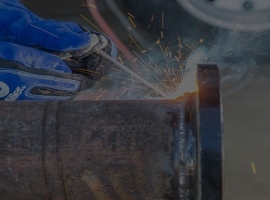
The most effective way to prevent porosity is to stop gas-forming contaminants from entering the weld pool in the first place. This begins long before an arc is ever struck. A rigorous pre-weld cleaning and material handling protocol is non-negotiable for critical applications like pressure vessel fabrication.
Base Material Preparation
All surfaces to be welded, including the joint faces and adjacent areas (at least one inch on either side), must be completely clean and dry. Any lingering contamination can vaporize in the heat of the arc and introduce gas into the weld.
- Degreasing: Use an appropriate solvent to remove all traces of oil, grease, and cutting fluids. Ensure the solvent itself has fully evaporated before welding.
- Mechanical Cleaning: Use wire brushes (stainless steel for stainless materials, carbon steel for carbon steels) or grinders to remove scale, rust, and any existing coatings like paint or primer.
- Moisture Removal: If the base material has been stored in a humid environment or is visibly wet, preheating is essential. Heating the material to a temperature of 100-150°C (212-302°F) will drive off any surface moisture.
Consumable Storage and Handling
Welding consumables are highly susceptible to moisture absorption, which is a primary source of hydrogen. Proper storage and handling are critical.
- Electrodes (SMAW): Low-hydrogen electrodes must be stored in a temperature-controlled rod oven according to the manufacturer's recommendations. Once removed from the oven, they should be kept in a heated quiver at the workstation. Any electrodes exposed to the atmosphere for longer than the prescribed period must be re-baked or discarded.
- Welding Wire (GMAW/FCAW/SAW): Keep wire spools in their original packaging in a clean, dry storage area until they are ready to be loaded onto the wire feeder. Once opened, protect the spool from dust and moisture.
- Welding Fluxes (SAW): Submerged arc welding flux is particularly hygroscopic. New bags should be stored in a dry environment. Once a bag is opened, the flux should be transferred to a heated holding hopper. Any flux that has been exposed to moisture must be re-dried in a flux oven at the temperature and duration specified by the manufacturer. At Oldwelders, our high-quality welding fluxes are produced from excellent raw materials like dolomite, bauxite, and cryolite, which are melted at 2000 °C to ensure purity and performance, but even the best materials require proper handling on-site.
Process-Specific Techniques for Porosity Prevention
While preparation is universal, each welding process has unique variables that must be controlled to ensure a gas-free weld. Supervisors should ensure their welders are trained on these process-specific nuances.
Submerged Arc Welding (SAW)
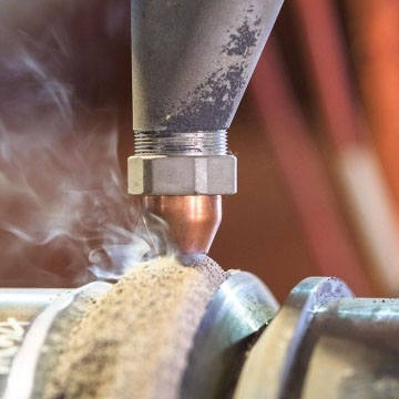
SAW is a go-to process for long seams in pressure vessels due to its high deposition rate. However, the granular flux that provides the shielding is also a potential source of moisture. Beyond proper flux handling, key parameters include:
- Voltage: Excessively high voltage can lead to a long arc, increasing the risk of atmospheric contamination and causing "arc blow," which can disrupt the molten flux blanket.
- Travel Speed: A travel speed that is too fast may not allow sufficient time for gases to escape the weld pool before it solidifies.
- Flux Burden: Ensure a sufficient depth of flux to completely cover the arc. An inadequate flux burden will result in poor shielding and likely lead to porosity. A high-quality flux, such as a specialized submerged arc welding flux hj431, provides a stable, protective slag for superior results.
Gas Shielded Welding (GMAW/MIG & GTAW/TIG)
For these processes, the integrity of the shielding gas coverage is paramount.
- Gas Flow Rate: Too low a flow rate provides insufficient coverage. Too high a rate can create turbulence, pulling atmospheric air into the shielding column. Check the manufacturer's recommendation for the specific wire/tungsten diameter and amperage being used.
- Equipment Checks: Regularly inspect gas hoses, fittings, and torches for leaks. A simple soap bubble test can identify issues. Check that the nozzle and contact tip (for GMAW) are clean and free of spatter, which can disrupt gas flow.
- Environmental Control: Even moderate drafts or wind (over 5 mph) can blow away the shielding gas. Use windbreaks or screens when welding outdoors or in drafty shops.
- Technique: Maintain a proper torch angle and a consistent contact-tip-to-work distance (for GMAW) or arc length (for GTAW). Pushing the torch (forehand welding) generally provides better gas coverage than dragging (backhand welding) in GMAW. Choosing the right mig-mag-tig welding machine with stable gas pre-flow and post-flow settings can also significantly improve shielding at the start and end of the weld.
Partnering with a Reliable Consumables Supplier
Ultimately, the consistency and quality of your final welds are directly tied to the consistency and quality of your welding consumables. Even with perfect preparation and technique, substandard wires, electrodes, or fluxes can introduce contaminants that lead to rejectable defects. This is why partnering with a proven, certified supplier is crucial for any serious fabrication operation.
As an ISO 9001 certified manufacturer, Oldwelders is committed to the highest standards of quality control. Our 1000-square-meter plant features six production lines capable of supplying 100 tons of welding consumables per day, ensuring we can meet the demands of large-scale projects without compromising on quality. This production capacity and commitment to quality have made us a trusted partner for fabricators in demanding international markets, including Brazil, Thailand, Australia, and Malaysia.
By sourcing your welding materials from a supplier with a robust quality management system, you minimize a significant variable in the porosity equation. You gain the assurance that each batch of consumables will perform predictably, allowing your team to focus on process control rather than troubleshooting material inconsistencies.
Inspection and Verification
The final step in any quality control program is verification. Non-destructive testing (NDT) is used to confirm that the preventive measures have been successful.
- Visual Inspection (VT): The first check. While it can only detect surface-breaking porosity, it's a quick indicator of a potential process issue.
- Radiographic Testing (RT): X-rays or gamma rays are passed through the weld to create an image on film. Porosity appears as dark, rounded indications. RT is very effective at detecting the size, shape, and distribution of subsurface porosity.
- Ultrasonic Testing (UT): High-frequency sound waves are introduced into the material. Pores and other discontinuities reflect the sound, creating a signal that can be interpreted by a trained technician. UT is excellent for detecting volumetric flaws within thick sections.
The acceptance criteria for porosity are defined by the governing construction code (e.g., ASME Section VIII for pressure vessels). Any porosity exceeding the size, number, or distribution limits specified in the code must be excavated and repaired. By implementing the systematic preventive measures outlined above, you can drastically reduce the frequency of these costly repairs, improving productivity and ensuring the long-term safety and reliability of your fabricated pressure vessels.